
Dual-Interface Card Milling & Embedding: A Complete Guide
Dual-Interface Card Milling & Embedding: A Complete Guide
Dual-interface cards combine the reliability of contact payment with the speed of contactless tap. They power bank cards, government IDs, transportation passes, and high-security access credentials worldwide. For manufacturers, the hardest part of making these cards is not the antenna or the chip alone — it is creating a precise cavity in the card body, placing the module exactly, and sealing the assembly without damaging the delicate contacts or the contactless inlay. This guide explains the dual-interface card milling and embedding process, what equipment each step needs, and how to choose machines that keep quality high and scrap low.
What Is a Dual-Interface Card?
A dual-interface card contains both a physical contact pad and a contactless antenna + chip. The card can communicate through the gold-plated pads when inserted into a reader, or through the embedded antenna when tapped against an NFC or RFID reader. The two interfaces share the same microcontroller, so the card behaves the same way regardless of how it is read.
The structure is more complex than a pure contact or pure contactless card:
- Contact interface — a module with exposed metal pads is embedded in the card surface.
- Contactless interface — an antenna loop and chip are laminated inside the card body.
- Interconnection — the chip inside the module is connected to both the external pads and the internal antenna.
Because the card must hold both systems without the antenna and contacts interfering, the production process demands tight tolerances and clean edges.
Why Milling and Embedding Are the Critical Steps
Dual-interface cards are built from multiple layers of PVC, PETG, or PC. Before the module can be inserted, a precise pocket must be milled into the front layer. The pocket must be deep enough for the module to sit flush with the card surface, but shallow enough to leave a backing layer that supports the contacts. A depth error of just a few hundredths of a millimeter can cause:
- Contact pads that sit too high and wear out quickly in readers.
- Pads that sit too low and fail to make electrical contact.
- Cracks in the backing layer that let the module detach.
- Scrap cards that fail ISO compliance testing.
After milling, the module must be inserted with precise placement, bonded, and sealed. That is why dedicated card cavity milling machines and IC module implanting machines are not optional extras in a dual-interface line; they are the core production equipment.
The Dual-Interface Card Production Flow
1. Sheet Printing and Lamination
The card artwork is printed on overlay films and assembled with the card core. For dual-interface cards, the core layer is pre-drilled or pre-cut for the antenna and chip placement. The layers are then laminated into a single sheet under heat and pressure. A flat, warp-free sheet is essential for accurate milling in the next step.
2. Cavity Milling
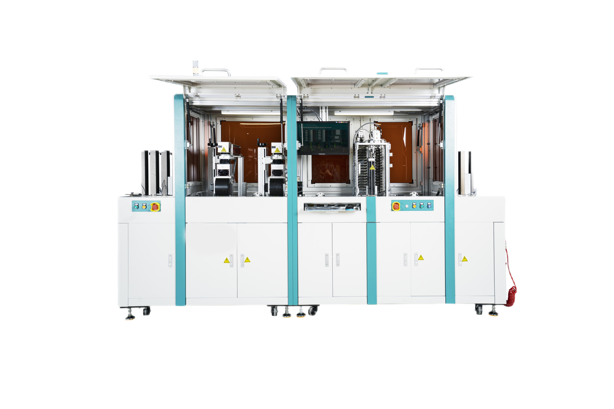
A smart card cavity milling machine cuts the module pocket into the laminated sheet. The machine uses high-speed spindles or router bits to remove material to a programmed depth. Key parameters include:
- Cavity depth — typically controlled to ±0.02 mm.
- Cavity size — must match the module exactly (ISO/IEC 7816 standard).
- Chip window — some designs require a separate, smaller window in the cavity base to allow the chip to contact the antenna.
- Chip-free zone — the antenna path must not be damaged by the milling process.
High-volume lines use a Smart Card Cavity Milling Machine to mill multiple cards per sheet in one pass.
3. Chip Implanting and Module Bonding
Once the cavity is clean, the module is placed into the pocket. The module contains the chip, contact pads, and connection leads. Depending on the card design, the machine may:
- Place the module and bond it with heat-activated adhesive.
- Connect the module leads to the antenna loop through the chip window.
- Apply a thin layer of protective tape or sealant.
This step is usually handled by an Automatic IC Module Implanting Machine or a combined Automatic Milling & Implanting Machine.
4. Sealing and Lamination
After implanting, the card surface is sealed and re-laminated to protect the module and antenna. The final lamination must preserve the flatness of the contact pad area while bonding the layers together. Any air bubble or raised edge will cause the card to fail insertion and withdrawal tests.
5. Personalization and Final Testing
The finished card is punched from the sheet, and the chip is loaded with keys, data, and applications. Electrical testing verifies that both the contact and contactless interfaces work correctly. The cards are then sorted, packed, and shipped.
Key Equipment for Dual-Interface Card Production
| Machine | Function | Typical Throughput |
|---|---|---|
| Cavity Milling Machine | Cut module pockets to precise depth | 6,000–12,000 cards/hour |
| Milling & Implanting Machine | Mill cavity and insert module in one system | 4,000–8,000 cards/hour |
| IC Module Implanting Machine | Place and bond modules into milled cavities | 3,000–7,000 cards/hour |
| All-in-One Pick, Place, Wire Embed & Weld | Combine antenna embedding, chip bonding, and welding | 2,000–5,000 cards/hour |
| Pick and Place Machine | Place chips or modules with vision alignment | High accuracy, flexible |
Throughput is only one factor. For dual-interface cards, placement accuracy, depth repeatability, and clean edges determine yield more than raw speed.
How to Choose the Right Equipment for Your Line
The best machine configuration depends on your product mix and volume:
- High-volume banking cards — a dedicated Smart Card Cavity Milling Machine paired with an IC Module Implanting Machine gives maximum throughput and tightest tolerance.
- Mixed-volume ID and telecom cards — an Automatic Milling & Implanting Machine combines both steps in a smaller footprint and reduces handling between stations.
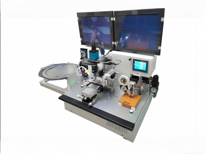
- Flexible prototyping or small batches — the All-in-One Pick, Place, Wire Embed & Welding Machine covers embedding, bonding, and welding in one unit, making it ideal for product development and low-volume runs.
- High-accuracy module placement — an Auto Patch Pick and Place Machine adds vision-guided placement for demanding modules or small components.
Common Defects and How to Prevent Them
- Module too high or too low — check cavity depth calibration and use pressure sensors during implanting.
- Antenna damage during milling — verify the antenna layout and keep the chip-free zone clear of the cutter path.
- Contact pad delamination — match the lamination temperature to the overlay material and avoid over-heating the module area.
- Intermittent contactless read — confirm the chip window size and the antenna connection quality after implanting.
Frequently Asked Questions
What is the difference between a contact card and a dual-interface card?
A contact card has only the metal pad interface. A dual-interface card has both contact pads and an internal contactless antenna, so it can be inserted or tapped.
Why does a dual-interface card need a cavity?
The module that holds the contact pads and chip must sit flush with the card surface. The cavity is the pocket milled into the card to hold the module at the correct depth.
Can one machine mill and implant modules?
Yes. Combined milling and implanting machines perform both steps in one system, reducing material handling and alignment errors.
What throughput should I expect?
Throughput ranges from about 2,000 units per hour for flexible all-in-one machines to over 10,000 units per hour for dedicated high-volume milling lines.
Which ISO standards apply to dual-interface cards?
ISO/IEC 7816 covers contact cards and module dimensions. ISO/IEC 14443 covers contactless operation. Cards must meet both to work reliably in real-world readers.
Conclusion: Match the Machine to the Process
Dual-interface card production is a chain of precision steps. Milling the cavity to the correct depth, implanting the module cleanly, and sealing the assembly without warping are the operations that separate a reliable card from a field failure. Buying the right equipment for each step — whether a dedicated milling machine, a combined milling and implanting system, or a flexible all-in-one unit — is the fastest way to improve yield and lower cost per card.
Planning a dual-interface card line? Explore ZOWINDA milling and implanting equipment or contact us at [email protected] / WhatsApp +86 186 2085 0485 for a line configuration review.
 How to Set Up a Smart Card Pro
 Antenna Embedding & Wire E
 Smart Card Manufacturing Proce
 RFID Inlay Sample Bonding Mach
Please contact us with your request
We are ready to answer your questions.